Below is the layout of the KTunerECU R1 Board. If you have an early unit you may not have additional pin labels on the board, but the pinout is the same. Please see below for additional pin breakdowns.
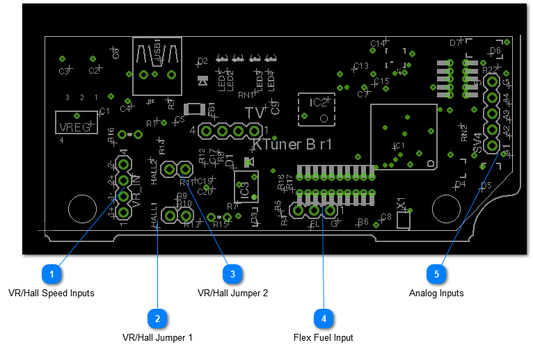
VR/Hall Speed Inputs
***In order to have the included wire leads plugged in to this port you may need to cut a hole in your ECU cover or get an available replacement cover with a cutout for this connector. If you're not using this set of inputs and don't have the leads plugged in then you do not need this cutout.***
Speed 1 Input
1+ used for Spd 1 VR+ or Hall input. Make sure the hall jumper 1 is set if using a hall sensor.
1- used for VR-.
2+ used for Spd 2 VR+ or Hall input. Make sure the hall jumper 2 is set if using a hall sensor.
On this three pin port the right two pins are used for flex fuel and this is included as a two pin connector on the board. The right pin is ground, the middle pin is for the flex fuel input.
A1-A4 are the analog inputs. They accept any 0-5v analog signal and can be configured in the software. G is a ground port if breaking out to an additional common ground is necessary.